Instant scale-up of small molecule pharmaceuticals: A case study in the multistep synthesis of anticancer drug Zanubrutinib with Accelerated microFactory technology
Nicholas A. Jose (1, 2), Akihiro Takada (3), Alexei A. Lapkin (2, 1), and Makoto Kawai (3), Kenji Yamawaki (3)
Summary
Development of new medicines is a very expensive process, which results in high cost of treatment to the consumers or national health services. As we are moving to more personalised medicines, even with the conventional small molecules – focusing on correct dosage and correct combinations of active ingredients for each patient – the cost of such customisation and the overall cost of the medicines discovery-development manufacture pipeline must be reduced significantly. One of the challenges along the way is how to make hundreds of grams to kilos of a new compound for pre-clinical trials when the chemical synthesis methodology that was used to make the first few milligrams of a substance for bio-activity testing has not yet been transferred to a larger-scale equipment. Utilisation of “digital manufacturing” technologies can help overcome these hurdles. By integrating robotic systems and intensified processing, scale-up becomes more like a “copy-paste” operation instead of weeks of manual labour, and allows rapid translation of the already developed small-scale experimental procedures to a scale that can produce the required amounts of a substance for the pre-clinical trials.
In a demonstration of this approach, Shionogi & Co. Ltd. and Accelerated Materials Ltd. devised a new approach for the synthesis of an anti-cancer drug intermediate. Using Accelerated’ MicroFactory technology, a bespoke hardware and software system for continuous production, a continuous throughput of 220 g per day was demonstrated within a single experimental trial, and valuable learnings were obtained further development and applications of digital manufacturing technologies in the pharmaceutical industry.
Abstract
As our understanding of diseases is improving, new drugs are sought for treating existing and emerging highly transmissible infections, treating and curing cancers, and treating increasing incidences of age-related diseases. The discovery and development of new drugs is a multifaceted activity. In this work we are targeting the development stage, when between 0.1-1kg of material is required for pre-clinical and initial clinical studies, and extensive characterisation. To obtain such a quantity of an active (pharmaceutical) ingredient (API) would typically require to re-develop a medicinal chemistry synthesis route that was used to produce the first few milligrams of an API, used in bio-activity testing, to a more scalable route, that would give the desired 1 kg of the material. For a number of years, the focus in pharmaceutical industry has been on using continuous flow technology for this scaling stage.1
Continuous flow equipment allows to handle syntheses with better control over operating conditions, resulting in better product quality, safe handling of hazardous conditions, and also easier automation, such that the equipment could be run un-attended 24/7. Typical flow chemistry equipment would represent a single reacting channel, whether it a tubular or packed bed reactors.2
There are some examples of plate reactors,3 or 3-D structured reactors,4 where a single feed stream is split into multiple channels inside a reactor to maintain the desired reactor hydraulic diameter and surface/volume ratio. This represent a strategy of ‘numbering up’ of reactors, when reactor dimensions are critical for performance (due to safety, heat transfer, light penetration or mixing performance). Such reactors would normally include a rather complex internal structure, designed to equilibrate flow across multiple smaller channels, since variation in flow rates among the parallel reactors would result in lowering of product quality.
Although such designs exist and are widely discussed in the literature, there remains a challenge of scaling continuous flow reactors to a desired space-time-yield (kg product per unit volume of a reactor per unit of time) through numbering up. Designs based on creating a pressure drop in the internal header within a reactor do not always provide the required flow uniformity and are prone to failures due to accidental blockages of some of the reactor channels. Such designs are working well in applications with less critical performance and no risk of fouling, such as multi-channel micro heat exchangers used in liquified natural gas transporting systems but have proven difficult to apply in the chemical industry.
For a period of time a concept of ‘smart scale’5 has replaced in popularity the idea of scaling by ‘numbering up’. ‘Smart scale’ is defined as the largest reactor size that allows to exploit the benefits of intensification without the need for numbering up. This concept is well illustrated by the cost-optimisation profile of a photochemical continuous flow reactor: the minimum of a cost function shows a very broad plateau over reactor diameter, enabling to identify the largest diameter that gives the optimal space-time-yield and minimum process cost.6 While ‘smart scale’ concept is a reminder that it is unnecessary to use very small reactors when the chemistry being performed does not require it, there still remains a challenge to effectively scale up continuous flow chemistry when small reactor diameters are absolutely unavoidable.
In this study, we present a robust “numbering-up” approach for rapid industrial pharmaceutical scale-up that simplifies the process of expanding continuous synthesis throughput. By increasing the number of continuous reactors to run in parallel with high precision, a pharmaceutical chemist may simply replicate the synthesis they conducted in a single reactor without additional experimentation.
In an industrial case-study, Shionogi Ltd. & Co. (SG) and Accelerated Materials Ltd. (UK) partnered through the Innovation Centre for Digital Molecular Technology (iDMT) in Cambridge to demonstrate such a scale-up using the Accelerated MicroFactory (AmF-S), a low-cost, fully automated numbering-up system for scaling from milligrams to kilograms per day. The system was used to transitioning the synthesis of a cancer therapy (Zanubrutinib) intermediate from ca. 10 g day-1 to ca. 100 g day-1 in a multistep synthesis. In-specification material (to within <1% standard deviation) was synthesized within a single run, and important lessons were learned for the improvement of continuous synthesis and AmF technology.
Introduction
The drug discovery process can take more than 12 years and cost more than EUR1Bn.7 Flow chemistry can shorten the drug design cycle times and attrition rates from months to days.8 It can also result in significant cost savings, flexibility, smaller footprint, and decreased inventory requirements.9 Although flow chemistry has been extensively used in drug discovery in small volumes, the implementation of flow-chemistry for scale-up is challenging due to several key issues.
To increase the production rate of a flow chemistry process there are two approaches – in the first, the size of a reactor is increased, and in the second, a number of tubes are placed in parallel, a concept known as “numbering-up”, see Figure 1. Increasing the reactor size (often the diameter of a tube, or the overall volume of a stirred tank), is common practice in chemical engineering and can be undertaken on the basis of dimensional analysis, i.e. through the conservation of dimensionless groups that control the overall reaction rate, which could be Re number, or mixing related parameters. However, dimensional analysis-based scale-up can overly-simplify the complex dynamics of a process,10 and additional engineering expertise and experimentation is still required to validate scale-up.
Numbering-up is attractive because all mass transfer parameters are conserved in the increased production volume, which can significantly simplify the scale-up process (as shown in Figure 2). However, this requires reagents to be distributed equally to many separate reactors. In extreme cases the ratio of a target overall plant throughput to a single channel throughput would result in the required number of reactors in the order of 104. Deviations in reaction performance between the channels mean that each reactor may be slightly different than another, resulting in an uncontrollable distribution of product quality. To alleviate this issue complex flow control must be employed to equally distribute reagents to each reactor.
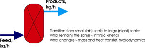
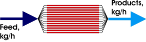
Figure 1. A schematic illustration of scaling by increasing in reactor size (top) vs scaling by numbering-up (bottom).
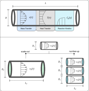
Figure 2. Various coupled phenomena in a typical flow chemical reactor (top) and the effects of increasing scale on process parameters via scale-out (dimensional analysis) and numbering-up (bottom)
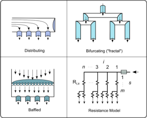
Figure 3. Depiction of various manifold designs and the commonly-used resistance model (bottom-right) for designing
manifolds.
A number of methods for achieving numbering-up exist, shown in Figure 3, which rely on engineered geometries to achieve a well-distributed inlet flow.11 The resistance model is a commonly reported method for simplifying the design and optimization of manifolds, in which the channels of a manifold are modelled similarly to electrical “resistors” in pressure drop calculations and optimization.
Clogging of reactors, a common issue in flow chemistry also presents a dynamic source of deviation.12 Controlling reagent distribution with such deviations requires a high amount of engineering expertise and can add to energy consumption within the process.13 Furthermore, few distribution strategies are generalized to optimize both the pressure drop and deviation in flowrate as a function of the manufacturing deviations in the downstream numbered-up processes, and are often custom-made to suite each process.2, 1
The Accelerated microFactory (AmF) technology platform is a suite of process technologies that streamline scale-up. AmF-S systems are used for scaling up from the milligram to kilogram scale. These consist of several unique components to make this possible:
- intensified, continuous flow reactors
- high-precision distribution systems, and
- bespoke automation protocols for control.
The AmF-S distribution system for numbering-up consists of unique, passive-regulating manifolds that require no external power input. These manifolds are engineered to compensate for downstream variations in reactor performance while minimizing the required pressure drop and can be generalized to a range of reactor configurations. AM’s design methodology enables rapid design and construction of passive-regulating manifolds for any downstream configuration. This methodology first consists of:
- Obtaining parallelized reactor characteristics
- Using our proprietary mathematical modelling tools to create an optimized manifold design
- Constructing the manifold to the desired manufacturing tolerance.
Our design for AmF-S manifolds consists of the following generic steps:
- Characterization of downstream variability (i.e. the % standard deviation in hydrodynamic resistance, σR).
- Specification of process operating tolerances (i.e. the % standard deviation in reagent flowrates σ, the flowrate in each unit Q and the number of units n).
- Design of the manifold with our proprietary modelling tools.
- Construction and calibration of the manifold.
As seen in Figure 4, which show simulations of manifold flowrate deviations across a wide range of parallelized channels (N), downstream deviations (σr) and flowrates, this methodology scales regardless of the flowrate, number of units or type of processes used downstream. To simplify our design process we have derived a design parameter Mp (or the “Multiplexing Number”), which describes the quality of improvement in flow distribution, log (𝜎/𝜎R). For example, in a process with a downstream deviation of 50%, to reduce the deviation in flowrates to 5% per manifold, i.e. log ( 𝜎 𝜎R ) = −1, such that a manifold with Mp ≤ 0 should be designed. In contrast to existing “resistance” based methodologies of designing manifolds, by varying Mp alone, one can optimize for reduced power consumption during pumping, thus lowering operational costs and carbon footprint. In some cases, as seen in Figure 4, such a design methodology may reduce the power requirements to achieve uniform flow by up to 40%.
In this work, the use of the AmF-S is demonstrated in the scale-up of the pharmaceutical compound Zanubrutinib,15 which is an active pharmaceutical ingredient for the treatment of lymphoplasmacytic lymphoma. via the inhibition of Bruton’s Tyrosine Kinase.16
This syntheses which were evaluated are schematically summarized in Scheme 1 and 2, where BG-4 is the precursor to the formation of chiral intermediates. The specific synthesis used in this study (see Scheme 2.) is an pathway for the synthesis for BG-4, which has been previously reported.17
The synthesis of Zanubrutinib is challenging to scale-up due to several factors. Firstly, as a recently developed molecule, information on synthesis kinetics is not readily available in the published literature. Second, Zanubrutinib possesses an asymmetric centre; in a non-selective synthesis, further purification via chiral assays (optical resolution) will reduce the maximum yield to as low as 50%. Finally, in this study we wished to scale-up an alternative route for synthesis which had not been previously examined in flow.
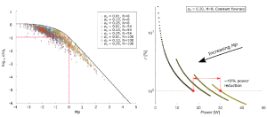
Figure 4. Manifold flowrate deviations as a function of the design parameter Mp over: (left) a range of downstream deviations, flowrates and number of parallelized channels, and (right) with constant downstream deviation, flowrate and parallelized channels.
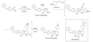
Scheme 1. Schematic of Zanubrutinib synthesis pathway, showing key intermediates, including BG-4.

Scheme 2. Schematic of BG-4 synthetic pathway and intermediates.
Methods
Apparatus The AmF-S configuration in this study, shown schematically in Figure 5, consists of three key modules: (i) a reagent delivery module, which is responsible for delivering a range of chemical ingredients and solvents throughout the system and monitoring outlet pressures, (ii) a reactor module, which can adopt a range of configurations depending on the quantity of product required, with adjustable backpressure and heating, and (iii) the automation module, which collects signals from the pumping and the reactor modules and processes user inputs to control the reagent delivery and the reactor.
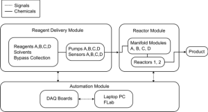
Figure 5. Diagram of the AmF-S system components.
Reagent Delivery Module
The reagent delivery module consisted of eight parallel syringe pumps (Tricontental C-3000 series) with 6-way valves on each, which is capable of simultaneously delivering up to four liquid reagents continuously at pressures up to 7 bar(g) in a a dual flow configuration, with low-pulsation. Each dual flow pump was connected to two inlets – a rinsing solvent and the reagent – and two outlets – a bypass vessel and the reactor module. This configuration enabled automated cleaning of the pumping system and reactor module. Pressure transducers connected to the outlet of the pumping module enabled real-time automated measurement of pressure, indicating the stability of flow rates, monitoring of possible clogging events and downstream monitoring of individual reactor flowrates.
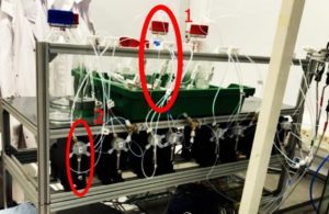
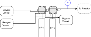
Figure 6. Reagent delivery module picture (top) and diagram (bottom), highlighting the placement of reagent bottles (1) and pumps (2), where SP-1 and SP-2 are a pair of syringe pumps operating continuously to pump either solvent or reagent through a six-way valve to either a bypass vessel or the reactor vessel, at which a pressure transducer (P) has been placed.
Reactor
Module Manifold
The reactor module consisted of reactor inlet manifolds and parallel flow reactors. Each reactor inlet manifold (A, B, C) consisted of a customized flow manifold (shown in Figure 7), which splits reagents from the pumping outlet into eight separate channels. AM’s manifold technology is designed using proprietary passive flow regulation devices, which are integrated directly within the manifolds. These passive regulators are specifically designed to reduce heterogeneity in flow distribution without the use of active electronic or physical components, such as valves. The AmF manifolds in this study were designed to distribute reagent flowrates based on the expected variance of downstream parallel operations while also minimizing pressure drop. They are also designed to continuously monitor the status of reactor flowrates to ensure uniform process operation. This is accomplished through the use of inline pressure transducers. In this study, the manifold module was made to be configurable for a wide range of tubing diameters, from 1.6 mm to 6.4 mm.
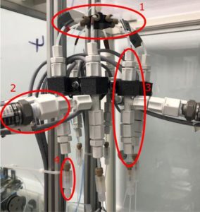
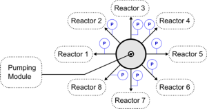
Figure 7. Manifold module picture (top), highlighting the distributor (1), pressure sensors (2) adjustable diameter t-fitting (3) and outlet connection (4). Manifold module for one reagent (bottom), showing the flow distributor (grey circle) which receives reagent from the delivery module, divides the flow into eight outlet streams, at which inline pressure transducers (P) have been placed.
In this study, the reactor module components (described further) had hydrodynamic resistances with a standard deviation of 5%, which could result in maximum deviations of up to 10% when mixing reagents, which may significantly affect product quality. The targeted variance in this study was 1%, or a reduction of 80% from the benchmark. Inline pressure transducers were placed at each of the manifold channel’ outlets during calibration such that the homogeneity of flowrates could be measured. With a calibration model of pressure drop vs. flowrate for each manifold outlet channel, individual flowrates could be estimated from the measured pressure drop between the pump outlet and manifold outlet.
Reactors
The parallel reactors were constructed from off- the-shelf PTFE tubing, mixers and hotplates. The reactor module had two configurations for S1 and S2/S3, each consisting of eight parallel units, which are shown schematically in Figure 8.
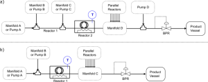
Figure 8. Schematic diagrams for individual reactor configurations for S1 (a) and S2/S3 (b), depicting t-mixers, heated coiled reactors (Reactor 2 and Reactor 1 in a and b respectively) with temperature sensing (T), and back pressure regulation (BPR).
In S1, a two-step reaction, reagents A1 and B1 were mixed in ETFE T-fittings with 0.5 mm inner diameters (IDEX CIL-P-632), which then fed into a length of 0.8 mm inner diameter PTFE tubing, 0.2 mL in total volume. This mixture feeds into another t-fitting of the same dimensions, mixing with reagent C1, which then fed into each reactor, which is length of 1.6 mm ID PTFE tubing with a total internal volume of 10 m, which were heated in automated hot oil baths. The outlets of these tubes were then combined using a manifold module after which reagent D1 was added to quench the solution. A back-pressure regulator was placed at the process outlet to ensure a reactor pressure of approximately 2 bar to prevent solvent boiling.
In S2/S3, which were one-step reactions, reagents A2/B2 and A3/B3 were mixed respectively in a T- fitting and fed into the same 10 mL 1.6 mm ID PTFE tube reactor used in S1, after which they were combined in a manifold module and collected.
Automation
The automation module controls all elements of the system, while recording pressures from the pumping and the manifold modules. Signal outputs from pressure transducers were connected to two electronic data acquisition devices (Arduino Mega 2560), which then sent data via a USB port to a laptop PC. The parallel hotplates and syringe pumps were also connected via a USB port to the same laptop PC.
The Flab coding framework (https://pypi.org/project/flab/) built by Accelerated Materials was used to coordinate the various routines governing actions, data acquisition and user interface. Flab is an open- source platform that enables the modular development of automated, complex routines involving multiple devices simultaneously.
A simple user interface was built in Flab (shown in Figure 9) which allowed for control of pump flowrates and flow directions, control and monitoring of hotplate temperature and stirring rates, and monitoring of reactor pressures and individual channel flowrates.
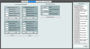
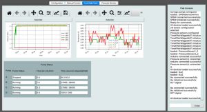
Figure 9. Snapshots of user-interface: manual input of reagent delivery and reactor conditions (top) and live display of reactor pressures and temperature (bottom).
Synthesis
The synthetic steps for producing BG-2, BG-3 and BG-4 (S1, S2 and S3 respectively) are shown schematically in Figure 10-Figure 12, which include flowrates, the calculated average residence times, concentrations, temperatures and pressures.
Prior to conducting parallelized synthesis, each synthetic step was optimized in a single reactor configuration. To scale-up, reactor temperatures and pressures were held constant, while flowrates were multiplied by the number of reactors used.
Each synthesis was conducted on successive days. Samples were collected every 0.25 to 1 h for high pressure liquid chromatography (HPLC) analysis.
Product quality was assessed by the normalized percent area (pa%) of the product peak. Product BG-2 was obtained after aqueous workup (a liquid/liquid extraction with water/ethyl acetate), concentrated in a rotary evaporator and dissolved in acetonitrile (MeCN) without further purification. Product BG-3 (172.7g) was also concentrated into a dark brown oily solid that was redissolved in MeCN and ethanol (EtOH).
Following S3, BG-4 was further purified by direct recrystallization by adding water in a semi-batch procedure, with slow dropwise addition.
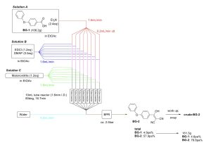
Figure 10. Schematic of S1 parameters, where EtOAc = ethyl acetate, EDCI = 1-(3-dimethylaminopropyl)-3- ethylcarbodiimide, DMAP = 4-dimethylamino pyridine, Et3N = triethylamine.
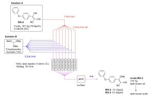
Figure 11. Schematic of Step 2.
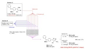
Figure 12. Schematic of Step 3.
Results & Discussion
Time-resolved measurements of product quality showed stable output of the reactors over S1, S2 and S3, as seen in Figure 13. S1 showed the most deviation (3%), which may be due to the increased variation in the two-step synthesis, or the result of uneven sampling of the quenched aqueous/organic mixture during analysis. S2 and S3 samples had deviations of 1% in %A.
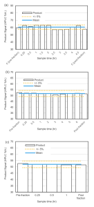
Figure 13. Time-resolved measurements of product quality in the synthesis of BG-2 (a), BG-3 (b) and BG-4 (c), depicting the mean product signal and 5% upper and lower bounds.
Notably, a significant amount of clogging formed during S3, resulting in a visually uneven distribution of liquid flow as seen in Figure 14. Despite this clogging, product quality remained consistent, indicating the ability of AM’s manifolds to robustly re-distribute reagents in the case of reactor degradation. Post synthesis, solids were found collected at the outlets of the T-mixers, which were the narrowest sections of the reactor.
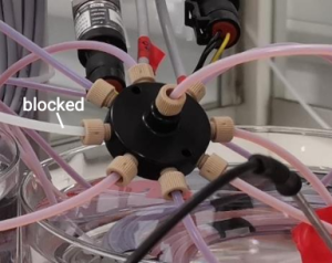
Figure 14. Image of a blocked channel in manifold D, where a purple colour indicates the flow of the product.
64.4 g (equivalent to a yield of 50.9%) was produced at the end of recrystallization. The yield is sufficient for a typical pre-clinical scale-up. Assuming three parallel modules were operated in a fully continuous fashion, with S2 as the limiting reaction step, the throughput is estimated to be approx. 220 g per day. A further parallelization to forty parallel units would be necessary to produce a kg per day.
Conclusions
In conclusion, we have demonstrated rapid scaleup of a multistep synthesis of Zanubrutinib intermediates. In this scaleup campaign deviations in product yield were reduced to as low as 0.9% during flow synthesis trials that ran for up to six hours. The effects of mixers clogging were mitigated through the use of the passive regulation manifolds.
At the same time, we have identified further development needs for the system: live monitoring of synthesis conditions, whether pressure or product yield, can be improved through inclusion of additional sensors, clogging is one of the most significant problems limiting the scope of flow chemistry, and new techniques for detecting and mitigating clogs are necessary, numbering-up with external modules can become organizationally difficult with the increasing number of reactors used, and internal configurations can be beneficial for instances in which more than ten parallel reactors are needed, other downstream applications also need to be considered, such as purification steps (concentration, filtration) and solids handling.
Acknowledgements
This project was enabled by funding from European Regional Development Fund (ERDF) for Innovation Centre in Digital Molecular Technologies.
References
(1) Hartwig, J.; Metternich, J. B.; Nikbin, N.; Kirschning, A.; Ley, S. V. Continuous flow chemistry: a discovery tool for new chemical reactivity patterns. Org. Biomol. Chem. 2014, 12 (22), 3611-3615, Article. DOI: 10.1039/c4ob00662c. Gutmann, D.; Cantillo, D.; Kappe, C. O. Continuous-flow technology – a tool for the safe manufacturing of active pharmaceutical ingredients. Angew. Chem. Int. Ed. 2015, 54, 6688-6728. DOI: 10.1002/anie.201409318. Sans, V.; Cronin, L. Towards dial-a-molecule by integrating continuous flow, analytics and self-optimisation. Chem. Soc. Rev. 2016, 45 (8), 2032-2043, Review. DOI: 10.1039/c5cs00793c.
(2) Lapkin, A.; Plucinski, P. K. Engineering factors for efficient flow processes in chemical industries. In Chemical Reactions and Processes under Flow Conditions, Luis, S. V., Garcia-Verdugo, E. Eds.; RSC, 2010; pp 1-43.
(3) Jensen, K. F. Microreaction engineering – is small better? Chem. Eng. Sci. 2001, 56, 293-303.
(4) Bavykin, D. V.; Lapkin, A. A.; Kolaczkowski, S. T.; Plucinski, P. K. Selective oxidation of alcohols in a continuous multifunctional reactor: ruthenium oxide catalysed oxidation of benzyl alcohol. Appl. Catal. A: Gen. 2005, 288, 165-174.
(5) Lueth, F. G.; Pauer, W.; Moritz, H. U. Properties of Smart-Scaled PTFE-Tubular Reactors for Continuous Emulsion Polymerization Reactions. Macromolecular Symposia 2013, 333 (1), 69-79, Proceedings Paper. DOI: 10.1002/masy.201300086.
(6) Loponov, K. N.; Lopes, J.; Barlog, M.; Astrova, E. V.; Malkov, A. V.; Lapkin, A. A. Optimization of a scalable photochemical reactor for reactions with singlet oxygen. Org. Proc. Res. Dev. 2014, 18, 1443-1454. DOI: dx.doi.org/10.1021/op500181z.
(7) Fletcher, A. J.; Edwards, L. D.; Fox, A. W.; Stonier, P. Principles and Practice of Pharmaceutical Medicine. John Wiley & Sons, Ltd: 2002.
(8) Lopez, E.; Alcazar, J. Flow Chemistry in Drug Discovery: Challenges and Opportunities. In Flow Chemistry in Drug Discovery, Alcazar, J., Hoz, A. d. l., Diaz-Ortiz, A. Eds.; Topics in Medicinal Chemistry (TMC), Springer, 2021.
(9) Porta, R.; Benaglia, M.; Puglisi, A. Flow Chemistry: Recent Developments in the Synthesis of Pharmaceutical Products. Org. Process Res. Dev. 2016, 20 (1), 2-25. DOI: 10.1021/acs.oprd.5b00325.
(10) Bisio, A. Scale-up of Chemical Processes: conversion from laboratory scale tests to successful commercial size design; Wiley, 1985.
(11) Shen, Q.; Zhang, C.; Tahir, M. F.; Jiang, S.; Zhu, C.; Ma, Y.; Fu, T. Numbering-up strategies of micro-chemical process: Uniformity of distribution of multiphase flow in parallel microchannels. Chemical Engineering and Processing – Process Intensification 2018, 132, 148-159. DOI: https://doi.org/10.1016/j.cep.2018.09.002.
(12) Baumann, M.; Moody, T. S.; Smyth, M.; Wharry, S. A Perspective on Continuous Flow Chemistry in the Pharmaceutical Industry. Org. Process Res. Dev. 2020, 24 (10), 1802-1813. DOI: 10.1021/acs.oprd.9b00524. Lapkin, A.; Loponov, K.; Tomaiuolo, G.; Guido, S. Solids in continuous flow reactors for specialty and pharmaceutical syntheses. In Sustainable Flow Chemistry – Methods and Applications, Vaccaro, L. Ed.; Wiley- VCH, 2017; pp 277-308.
(13) Saito, Y.; Kobayashi, S. Recent Advances of Asymmetric Catalysis in Flow for Drug Discovery. In Flow Chemistry in Drug Discovery, Alcazar, J., Hoz, A. d. l., Diaz-Ortiz, A. Eds.; Topics in Medicinal Chemistry, Springer, 2021.
(14) Dong, Z.; Wen, Z.; Zhao, F.; Kuhn, S.; Noël, T. Scale-up of micro- and milli-reactors: An overview of strategies, design principles and applications. Chemical Engineering Science: X 2021, 10, 100097. DOI: https://doi.org/10.1016/j.cesx.2021.100097.
(15) EMA. Brukinsa. European Medicines Agency, 2021. https://www.ema.europa.eu/en/medicines/huma n/EPAR/brukinsa (accessed 26.07.2022).
(16) Guo, Y.; Liu, Y.; Hu, N.; Yu, D.; Zhou, C.; Shi, G.; Zhang, B.; Wei, M.; Liu, J.; Luo, L.; et al. Discovery of Zanubrutinib (BGB-3111), a Novel, Potent, and Selective Covalent Inhibitor of Bruton’s Tyrosine Kinase. J. Med. Chem. 2019, 62 (17), 7923-7940. DOI: 10.1021/acs.jmedchem.9b00687.
(17) Hu, N. Use of a combination comprising a BTK inhibitor for treating cancers. 2018, WO 2018/033135 A1.