Semiconductor Application
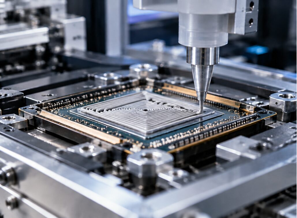
Thermal Interface Materials
High thermal conductivity with electrical insulation where required.
Discuss your specification
Relevant Materials

Aluminium nitride is the primary material page for the electrically insulating TIM opportunity.

01

Aluminium Nitride

AM has demonstrated wurtzite AlN with sphere/rod primary particles at approximately 200 nm to 1 µm, providing a strong starting point for thermal-interface formulation development.

02

Zinc Oxide

A morphology-rich functional oxide for selected electronic formulations where ZnO functionality is specifically required.

The thermal bottleneck

The thermal interface is critical

TIMs replace low-conductivity air gaps and accommodate surface roughness between heat-generating semiconductor structures and the next heat-spreading surface. The relevant metric is the assembled interface performance at the intended bondline, pressure and reliability condition, not the bulk conductivity of the filler alone.

Where electrical isolation is required, ceramic fillers must form efficient thermal pathways without creating an electrically conductive network. Particle packing, agglomeration, surface treatment, loading and matrix compatibility therefore have to be engineered together.
TIM Architecture

TIM1, TIM1.5 and TIM2 place different demands on the material

TIM1 · die to lid or heat spreader

Thin bondlines and high heat flux make low interfacial resistance, controlled coverage, pump-out resistance and compatibility with die and lid surfaces critical.

TIM1.5 · bare die to heat sink or cold plate

Direct contact to the cooler can reduce interfaces, but the material must accommodate mechanical tolerances while protecting the die and maintaining controlled thermal contact.

TIM2 · lid to heat sink or cold plate

Larger areas and larger tolerances usually place more emphasis on gap filling, compliance, compression behaviour and long-term stability.
Filler Engineering

Established TIM design starts with packing, interface resistance and electrical requirements

Industry TIM formulations commonly use electrically insulating ceramic fillers such as aluminium nitride, boron nitride and alumina. AM has demonstrated AlN particle synthesis with a direct fit to thermally conductive, electrically insulating interface formulations.

Aluminium Nitride

AM has demonstrated wurtzite AlN with sphere and rod primary particles at approximately 200 nm to 1 µm. It combines thermal conductivity with electrical insulation and provides a strong starting point for application-specific TIM development.

ZnO · selected functional use

ZnO can be useful in multifunctional electronic composites, but it should not be presented as a default replacement for high-insulation AlN, BN or alumina in demanding TIMs. Its use should be driven by a specific formulation target.

Packing and agglomerate control

A multimodal distribution can improve packing, but the largest effective agglomerates must remain compatible with the minimum bondline and dispensing route.
Advanced IC Packaging

Particle control becomes a flow and reliability problem as well as a chemistry problem

In advanced packaging, the smallest gap can set the maximum tolerable filler or agglomerate size. Chiplets, 2.5D and 3D integration increase the number of interfaces while reducing pitch, stand-off and flow paths.

Capillary underfill

Filler size, agglomeration and viscosity influence wicking speed, filler transport and void-free coverage beneath the die.

Compression molding

Fine filler technology, loading and flowability affect mold fill, warpage and local resin/filler uniformity.

Fine-pitch bonding

Thermocompression and related processes require compatible underfill or non-conductive paste behaviour around tightly spaced bumps and Cu pillars.
What to Qualify

Particle analytics must be connected to the assembled thermal stack

Primary-particle and agglomerate distributions, with explicit control of the coarse tail.

Morphology, phase identity and purity appropriate to the electrical-insulation requirement.

Viscosity versus shear rate, yield stress, settling stability and filler loading in the real formulation.

Bondline thickness, void content and thermal resistance after dispense, assembly and cure.

Temperature cycling, power cycling or extended high-temperature exposure appropriate to the target package.
The AM development route

Optimise the particle population against the actual formulation and bondline, then preserve the qualified formation window as capacity increases

K1 · Filler discovery

Map precursor and process conditions against phase, size, morphology and dispersibility, then screen loading and rheology in the intended matrix.

K10 · Formulation validation

Generate repeat lots for high-loading mixing, dispensing, cure, thermal resistance and electrical-insulation testing.

K100 · Manufacturing supply

Increase material output while holding the particle and agglomerate specification used during qualification.

Start with the thermal stack

Bring your specification

Share the package surfaces, TIM location, target bondline or gap, required thermal resistance, electrical insulation requirement, resin system, viscosity window, cure conditions and reliability environment.

Get in Touch

This field is for validation purposes and should be left unchanged.